Retaining Wall
The chosen retaining wall design is a precast concrete wall. This was chosen due to its structural strength. Due to a large surcharge being applied to the retaining wall, it is necessary that the wall be strong enough withstand surcharge. The worst case scenario was taken into consideration to ensure that that the walls are able to withstand the maximum active surcharge that could be applied. Passive surcharge, located at the face of the wall, was neglected to design according to the worst case scenario. The passive surcharge acts in such a way that counteracts the active surcharge. Therefore, to design conservatively, this value was neglected.
Retaining Wall Dimensions
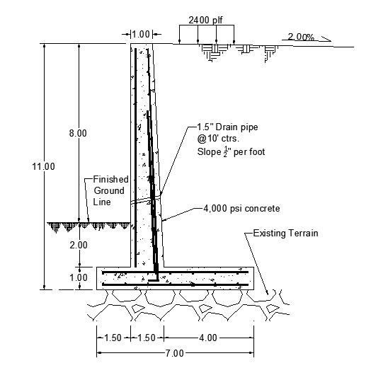
The design of the retaining wall was performed primarily through a program called ASDIP cantilever retaining wall. This program determines whether or not a wall of certain dimensions can withstand the forces applied. To use this program efficiently, several things needed to be determined. It was determined that the elevation of the RDC would stand at 8 ft. as discussed in the layout design. Along with a 2 ft. soil cover, the backfill height/stem height comes to a total of 10 ft. tall. A key was not required for this design because the surcharge did not create enough sliding to merit one. The dimensions of the retaining wall can be found below.

Soil Properties
Properties needed to design the retaining wall gathered from the geotechnical report given to us by Cinder Lake Landfill. The properties from the report:
Backfill Moist Density: 117.4 pcf
Backfill Saturated Density: 130 pcf
Soil Classification: Silty Sand (Internal friction angle of 35 degrees was assumed given this information)
Allowable Bearing Pressure: 15.2 ksf
Friction Coefficient: 0.4
Water Table is Negligible
Other details needed for an accurate design:
Maximum weight is a result of a 962K Medium Wheel Loader with a weight of 45,055 lbs. Surcharge was calculated as 200 psf.
Retaining Wall Materials
The materials of the wall were the most important components of the wall. If too weak of materials were chosen, then the wall would crumble and if too strong of materials were chosen, then the wall would be overpriced for what it needed to do. The concrete that was chosen had a compressive strength of 4,000 psi and the rebar strength is 60,000 psi.

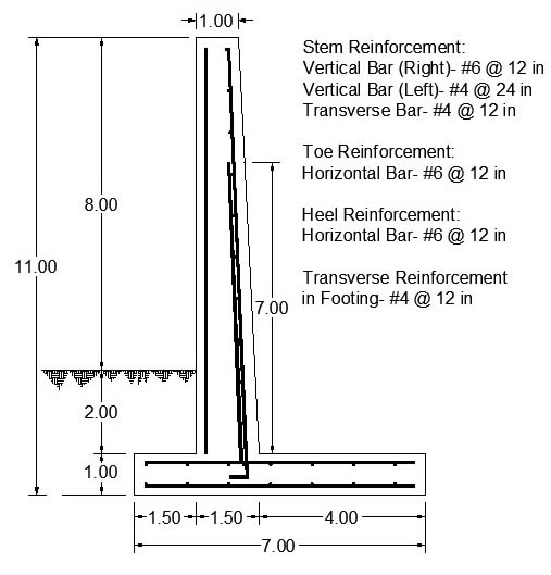
Description: #6 rebar was used at a spacing of 12 in. on the right side to prevent shear failure. A #4 bar spaced at 24 in. was place on the left side of the stem, as shown in the construction drawings. This rebar was placed in the design in order to account for the possibility of seismic activity. The heel and toe horizontal rebar were #6 bars at a 12 in. spacing. The transverse bar size used for both the stem and footing were #4 bars spaced at 12 in. apart. This reinforcement was necessary to prevent failure due to shear.
Checks
All of the retaining wall checks were important in determining if the wall designed above could withstand the loads applied. The checks that needed to be done included the overturning safety factor, the sliding safety factor, the shear force ratios, and the moment capacity ratios. Each of these checks had certain values that they needed to be less than or greater than in order to meet the requirements.
Stability Checks:
Overturning Safety Factor: 3.50 > 1.50 ok!
Sliding Safety Factor: 2.21 > 1.50 ok!
Shear Force Ratio (Vu/ФVc):
Stem: 0.23 < 1 ok!
Toe: 0.26 < 1 ok!
Heel: 0.76 < 1 ok!
Moment Capacity Check:
Stem: 0.43 <1 ok!
Toe: 0.23 < 1 ok!
Heel: 0.95 < 1 ok!
With all of the checks completed, the retaining wall is completed and prepared for implementation into the design of the RDC.